Y plan
This scheme uses a 3 port mid position valve. In the past this was by far the most common setup, as it only requires one valve.
It can still be fitted today, however is not suitable for systems with more than one heating zone.
3 Port Valve Operation
The valve itself has three plumbing connections - in, out A and out B.
Regardless of other settings, at least one of the outlets is always open, so it is always possible for water to flow through the valve.
Outlet A is normally connected to the central heating, with B used for hot water.
Electrically, the valve has 5 wires:
- Green/Yellow, Earth - connected to the metal body of the valve.
- Blue, Neutral - internally connected to the neutral side of the motor.
- White, Live in 1 - Activates the motor inside the valve to select either AB (both) or A (heating)
- Grey, Live in 2 - Used with the White wire to select outlet A only (heating)
- Orange, Live Out - this is used to switch the boiler on when the valve is at position A.
No power
With no power applied, the spring holds the valve in position B, so water only flows to the hot water cylinder.
Power on White only
The motor will move the valve to the mid position AB, so both heating and hot water are selected. Internal switches and other components ensure the motor is held at this mid point.
Power on White and Grey
Here the motor will move to position A (heating only). When it gets there, an internal switch connects white and orange together, and this output is used to activate the boiler.
This results in a noticeable delay when switching on heating only, as the motor has to move the valve from B to A. This takes several seconds.
Overview Video
This video covers the wiring and electrical operation of a Y plan system. Wiring diagrams and further information continues below. View on Youtube.
System Wiring
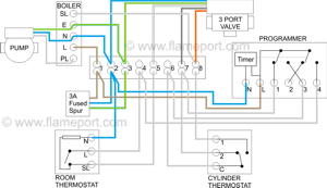 This diagram shows the wiring layout using the most typical components. Here, coloured wires indicate the permanent mains supply to the boiler and programmer. The three additional coloured valve wires are also shown (white, grey and orange).
Other wires are shown in pale grey. Some or all of these will be live depending on which modes are selected - these are highlighted brown in the other diagrams below.
These diagrams show a modern boiler where the boiler requires mains power all the time, with a separate wire used to activate the boiler and the pump connected directly to the boiler.
Older systems simply have the boiler and pump connected to SL (8 in the wiring centre), with only N and E permanently connected.
The room thermostat is shown with a neutral connection. However a 2 wire thermostat can be used which does not require a neutral.
Operation - Hot water only
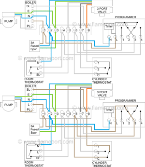 Power starts at terminal 3 (HW On) in the programmer. This passes via the wiring centre terminal 6 to the cylinder thermostat. If heat is required, power continues to terminal 8 in the wiring centre, and on to the boiler and pump.
The valve is not powered at all, and the spring holds it in position B, so water from the boiler only flows to the hot water cylinder.
Note that although the orange valve wire is connected to power, this does nothing, as orange is only connected via an internal switch when the valve is in position A.
Operation - Hot water and central heating
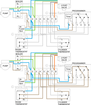 Here, power is also applied to programmer terminal 4, which connects via wiring centre terminal 4 to the room thermostat. If heat is required, power continues to terminal 5 in the wiring centre, and therefore to the white valve wire.
This causes the valve motor to move to the mid position, and water from the boiler flows to both the hot water cylinder and the radiators. As with hot water only, the orange valve wire is connected to power via the wiring centre terminal 8, but orange is still not connected to anything inside the valve.
Operation - Heating only
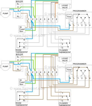 The only addition to acheive heating only is terminal 1 (HW Off) of the programmer being connected to power.
As programmer terminal 1 has power, so does wiring centre terminal 7 which is connected to the valve grey wire. The white wire already has power via the room thermostat, and as power is applied to both grey and white, the valve moves to position A.
This is where the orange wire is required - when at A, orange is internally connected to white, and terminal 8 in the wiring centre receives power, activating the boiler and pump. As a consequence of this, power also returns via the cylinder thermostat to the programnmer 'HW On' terminal. However this does not change anything.
The same result is acheived if the hot water cylinder is fully heated - the cylinder thermostat provides the 'HW Off' signal by connecting C and 2 together.
Due to several seconds being required for the valve to move from B to A, there is a delay between selecting heating at the programmer and the boiler starting.
Possible problems
As correct operation relies on the valve internals functioning properly, valve failure will result in some non-obvious situations.
Heating only does not work
If the switch in the valve fails, the orange wire will never be connected to power. This results in heating only not working at all, yet the system works fine with water only or heating and water.
Radiators never heat up, regardless of other settings.
If the valve motor fails, the valve will remain at position B and hot water will never reach the radiators.
Radiators and hot water always work together
Usually this shows up in the summer when hot water only is required. Caused by either the valve sticking in the mid position, or the lever on the side being in the 'manual' position.
On most valves, the actuator head containing the switches and motor can be replaced as a separate unit without draining the system. On some, the internal motor can be replaced, although it is often easier to change the whole head.
If the valve itself sticks or fails, the solution is either to replace the entire thing, or on some makes the internal valve ball and spring can be replaced.
Hive and other similar 'all in one' systems
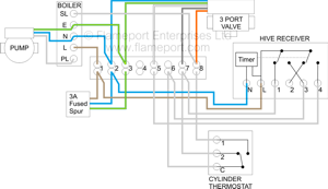 These systems contain a wireless controller with a wired receiver unit. The receiver unit replaces the existing programmer. The wireless controller contains a room thermostat and is used to control both the heating and hot water, so any existing wired room thermostat must be removed.
Wiring is essentially the same as a standard Y plan, with the room thermostat removed and the controller unit replacing the programmer. Hot water thermostat, valve, boiler and pump are unchanged.
