Combination Boilers - External Programmer and Thermostat
An external programmer or timer is fitted where the boiler does not have a integral timer.
Volt Free
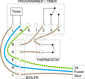
 In order to work properly, the programmer and thermostat must be wired in series. For volt free switching, the circuit starts at the boiler terminals, passes through the programmer, then through the thermostat, and returns to the boiler. The boiler will only operate when both the programmer and thermostat are on.
The diagram shows a typical programmer. In this design, the terminals 2 and 4 are connected together when the programmer is on. The programmer requires a permanent mains supply which should be taken from the boiler terminals. This ensures the complete system can be isolated using the 3 amp fused spur.
Note the programmer only requires mains power to operate - there is no connection between the mains wiring and the programmer switch terminals.
Mains voltage switching
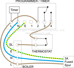
 In this design, the wiring is substantially similar, however note the connection between L and 2 in the programmer. A few programmers have this link internally, but usually it must be added by the installer.
In this arrangement, power is supplied to the boiler and programmer via the 3A fused spur. Terminal 2 of the programmer is permanently connected to line. With the programmer on, terminal 4 is also connected to line. If the thermostat is also activated, the SL terminal on the boiler is connected to line, and the boiler operates.
This is the same operation as the volt-free system, except in this case, line voltage is applied to the controls and boiler. The boiler only operates if both the programmer and thermostat are on.
3 wire thermostat and programmer
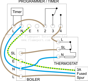
 This is the same switching arrangement, however here a 3 wire thermostat is used, which requires a neutral connection. Here, the neutral is shown from the boiler, however it could be provided via the programmer if this is more convenient.
Programmers
A wide range of programmers and timers is available, however they all work in the same way - a pair of terminals is connected together when the device is set to on.
The example here shows the switch between terminals 2 and 4, however this will vary. Always check the instructions supplied with a programmer.
Mains voltage only
Some programmers, particularly older ones, have a permanent link between line and the common terminal (2 in these examples). While this is convenient for mains systems, it does mean the programmer cannot be used for volt-free switching.
Standard backplate
Most programmers fit onto a standard backplate, which has L,N,E and four numbered terminals. While the plate is physically identical, the wiring may not be. Always check the wiring carefully when replacing any programmer - assuming it is the same can easily lead to damage and destruction.


