Frost Thermostats
Installing a pair of thermostats to prevent damage from frost or freezing temperatures.
Overview Video
This video covers wiring for frost thermostats on S plan, Y plan and combination boilers. View on Youtube.
A description and diagrams used in the video continues below.
Components and Overview
Two thermostats are used, the first being an air sensing thermostat. This should be installed in the coolest part of the building, typically on the ground floor. If parts of the heating system extend to areas likely to be much colder such as garages or conservatories, the thermostat should be installed there.
This thermostat activates when the air temperature falls, typically below 5C.
A second thermostat is installed on the heating return pipe at the boiler. This activates below about 30C.
In the video and diagrams below, a Honeywell T4360A frost thermostat and Honeywell L641B pipe thermostat are used. However any frost thermostat that can be set to 5C and a pipe thermostat with a range of about 10C-40C could be used.
Operation
- When the ambient air temperature drops below 5C, the thermostat contacts close and the boiler is activated.
- The boiler heats the water in the pipes and circulates this water throughout the system.
- Once the return pipe to the boiler reaches 30C, the pipe thermostat switches the system off.
- This cycle repeats once the pipe has cooled, assuming the air temperature is still below 5C.
A single air thermostat would work, however that would use significant amounts of fuel as the air temperature would need to rise above 5C. That would require the boiler to run for much longer and heat the radiators to a much higher temperature.
Although not shown in the diagrams, the cable to each thermostat would normally be 3 core, the 3rd core being used as the circuit protective conductor (earth).
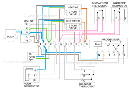
S Plan
 The objective here is to connect the permanent line (terminal 1) to the heating on (terminal 5). This will activate the heating regardless of any other controls.
The thermostats are wired in series, wiring shown in pink on this diagram. The link between the two thermostats is done at a spare terminal in the wiring centre, 9 in this example.
This allows a separate cable to be used for each thermostat, as they would typically be in different locations.
The heating system is activated only when both thermostats are closed - air temperature below 5C and pipe temperature below 30C.
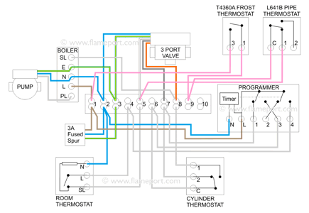
Y Plan
 Wiring for Y plan is almost identical - the only difference is that the wire from the thermostat on terminal 5 connects to the white valve wire.
The white wire selects heating, the valve moves to the heating position, and the boiler is activated via the orange output wire.
As with the S-plan arrangement, the heating system is activated only when both thermostats are closed. The frost thermostats also override any other controls.
Combination Boilers
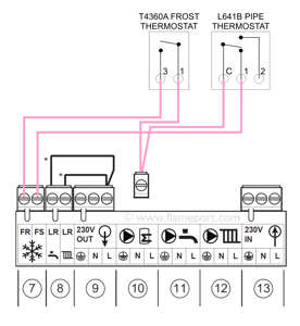
 Combination boilers are all-in-one devices, and typically do not have any external wiring. However the same frost thermostats in the S-plan and Y-plan examples can be used, wired directly to the boiler.
The diagram here shows terminals in a Worcester Bosch combi boiler, labelled FR and FS. Connecting those together activates the boiler.
Most combination boilers have similar terminals.
The connection between the two thermostats is shown as a separate terminal block - this can either be added inside the boiler, or an external junction box could be used.
On some combination boilers the frost terminals activate the heating. Others will only activate the circulation pump initially, but will then activate the heating if the water temperature as determined by the boiler's internal sensors falls below a certain value.
Boiler only?
Many boilers have built in frost protection, and will activate if the temperature internal to the boiler falls below a certain value.
This can be sufficient in many cases, but is only valid if the boiler is located in the coolest part of the building.
A boiler located in an upstairs insulated airing cupboard would not protect against freezing pipes on the floor below, or where pipes pass through a garage or other colder space.


