Photos from 2018
2018 electrical installations by Flameport Electrical
Pump Control Panel - Old and New
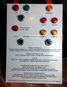
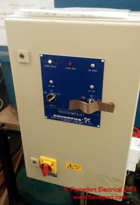 This is a control panel for a pair of water pumps, these supply water to a block of flats.
The original panel was about 15 years old, and had been partly broken for several years, hence the brown tape over one of the controls.
The failure was an electronic controller, one channel of which no longer worked. The controller was obsolete, and the nearest equivalent replacement was not directly compatible so would have required other components to be replaced as well - probably an entire new control panel.
A timer had been fitted to the outside to switch between the two pumps at intervals, relying on the remaining working control channel to activate the pump. However this also became unreliable, and at times would leave the pump running continuously for hours, causing excessive wear and wasting electricity (these are 2.2kW pumps).
Pictures here show the original panel and the new front panel before installation.
Pump Control Panel - Underway
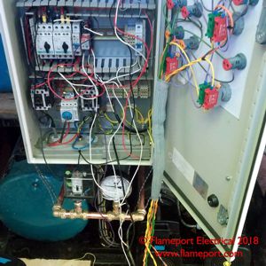 This shows the panel partly rewired. A new pressure switch and indication gauge have been fitted below the panel. The original gauge was installed out of sight and upside down at the back of the pressure vessel (green item lower left). It was also broken and therefore entirely useless.
Originally the pressure sensor was an electronic type, and the original intent being that either one or both pumps could be activated depending on the pressure drop. However for this installation running on both pumps has never been required, and it had been operating without issue for several years with just a timer switching between the two pumps at intervals.
The new pressure switch is a mechanical on/off device with adjustable set points - square box directly below the panel to the left of the pressure gauge. The gauge is for visual indication only, as a quick confirmation that the system pressure is correct.
Pump Control Panel - Complete
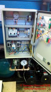
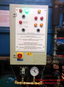 The completed panel is shown here. Instructions for manual override have been added to the panel, a significant improvement to the piece of paper left hanging by the original panel.
Internally, the original controller has been removed and a timer installed at the top which switches between each pump at intervals. When the pressure drops below the set level, the pump is activated until the pressure rises above the upper set level.
Controls on the front can select a single pump only (for where one pump has been removed for maintenance), or auto switching between both via the timer.
Contactors, overloads and several other smaller items were reused from the original panel, including the water level detector which deactivates both pumps in the event of the water tank being empty.
Pump Control Panel - Further Information
This panel and it's construction is featured in a series of videos on Youtube.
Phase Converter Repair - Before
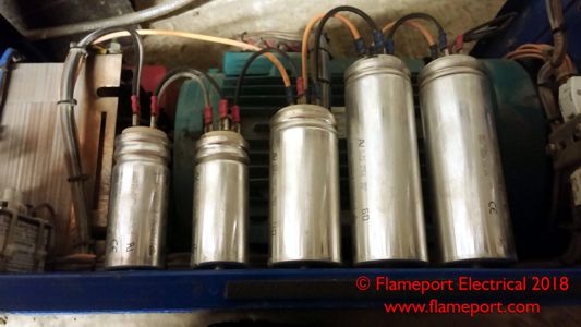
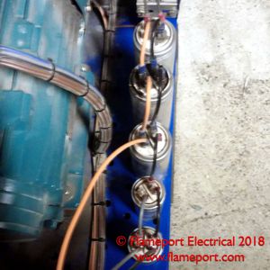 This is a rotary phase converter - a device that takes single phase input and provides 3 phae output. Used to operate 3 phase equipment where only a single phase supply is available.
This had been running for many years and the capacitors inside had failed (the silver can shaped objects). Several of them are leaking on the top, as can be seen by the black oily residue around the wiring connectors.
The symptoms were that the motor in the equipment this supplied was running very noisily and overheating, as the output voltages were no longer properly balanced.
Phase Converter Repair - After
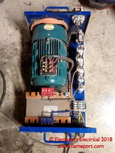 This shows the new capacitors installed.
This is another example of where the repair was far less expensive than buying a new device.


